This thread is to document timing considerations in the MEG, primarily delays for various stimuli and devices. It will likely be a work in progress for a while.
Audio
Delays: 6.2 ms from the computer, 5.0 ms from the speakers & ear tubes
In PsychToolbox (Matlab), there appears to be a 6.2 ms delay between the requested presentation time of a sound, and the actual playback start time reported by PTB. This would depend on the details of the task code and should be verified, but gives an idea on what to expect for delays inside the computer (Matlab, Windows, audio drivers).
Once the sound is output, there is a further 5 ms delay for the sound to reach the ears. This was measured by recording the original sound in a MEG analog channel (which is the recommended approach to measure onset times for all sounds), and using a microphone to record the sound at the tip of the ear tubes, also in an analog channel. While the latter is noisy, averaging trials and using cross-correlation gives a clear result: a difference of 12 samples at 2400 Hz = 5 ms. Note that the signals are flipped with respect to each other in this speaker/microphone setup.

Video
Delays: 8.33 ms (at 120 Hz frame rate) after pixel mode event marker
The PROPixx projector has a “pixel mode” which sends the color values from the top left pixel to a digital input channel in the MEG. These codes are sent exactly 1 frame (8.33 ms @ 120 Hz) before appearing on the projector screen. For visual stimuli, it is recommended to encode information in this top left pixel to record their onsets, e.g. the simplest is to add a 1-pixel wide white box to the visual stim(s) of interest, and black at every other time. This replaces the use of a photodiode, but we have to account for the constant 1 frame delay.
Digital channels and triggers
Delays: about 4 samples (1.7 ms at 2400 Hz) earlier than all analog channels, practically always safely ignored
All analog channels (MEG, EEG, ADC) are filtered in the hardware to prevent aliasing, when going from the initial high sampling rate to the one selected for the recording (we typically use 2400 Hz). This causes a group delay of about 4 samples. While this delay is complicated and varies for different frequencies, it is small and practically never of concern. Digital channels are not filtered but instead apply a “bit-wise or” operation when down-sampling, such that all signals are kept even if they are only present for a fraction of a sample.
Similarly, triggers defined in the acquisition software configuration by a threshold on an analog channel, e.g. audio recorded on an ADC channel, are detected early in the processing, before down-sampling occurs, and are thus also ahead of the analog signals by about 4 samples. This is easily seen by comparing the trigger time with the moment the signal (recorded in an analog channel) actually crosses the defined threshold for the trigger.
Tactile stimulator
Delays: 75 ms after the valve event marker
Our custom-made tactile stimulator uses an Arduino to communicate with the stimulus computer and trigger a solenoid valve on demand. The valve opens for a short duration which sends a pulse of pressurized air down a long tube to a finger clip. The voltage going to the valve is what is captured in a MEG analog channel to generate event markers. There is therefore no delay from the computer itself, only from the valve and the time it takes for the pressure pulse to make its way to the finger clip.
The delay was measured with a microphone on the finger clip to capture its movement, recorded in a second analog channel, as we do normally for audio. The result indicates that the clip motion (tap on finger) occurs 75 ms (± 2ms) after the event marker.
[To-do: add pic from test data, around 2023-10-11]
Response buttons
Delays: none expected from the device and electronics, variable between muscle contraction and enough finger and button motion to trigger, around 20-40 ms when averaging.
For now, we do not expect any delays from the buttons themselves or the electronics, i.e. the VPixx response button box and electrical connections to the MEG digital input ports. There are of course biological delays: brain > muscles > motion, as well as small delays from the initiation of finger motion to the point where the button triggers. This was however minimized during the (in house) design of the pads. It may still be of interest to quantify the latter delay, using an independent measurement of motion onset, like an accelerometer or EMG. (See below for an example of EMG data.)
There may be three slightly different ways to get event markers that represent button presses.
- Buttons > ResponsePixx box > MEG parallel port 1
- Buttons > ResponsePixx > DataPixx > MEG general input-output port
- Buttons > ResponsePixx > DataPixx > Stim computer task > MEG parallel port 2
Method 1 is direct and should be preferred for accurate timing, though method 2 should have practically identical timing. Method 3 depends on the task program and code (e.g. PsychToolbox/Matlab script), and is usually used to provide additional information such as correct/incorrect responses, or duplicates, false alarms, etc., which cannot be determined without the task context.
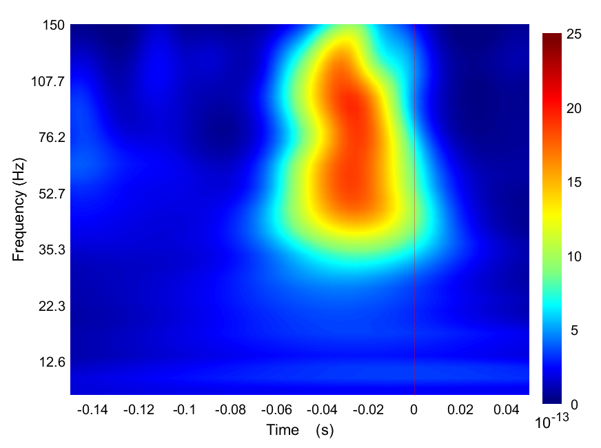
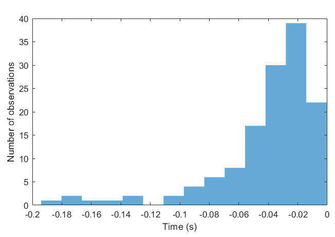
As an example, here are some data showing the relative timing with a simple index button press task, where time zero is the button triggering. The first image shows the averaged time-frequency plot, to get an idea of the best frequency band to use to view the EMG and potentially use it for semi-automatic event marking. The second figure shows the timing of the peak of EMG activity preceding the button press across trials, showing the variability.