6 Complete Menu Reference
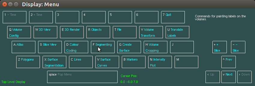
The following is a complete listing of every menu selection, with a short description of each function. Since this program is also partly a research tool, a few selections are not relevant to most users, and will simply be described as not for general use. Figure 2 shows the top level menu that is presented upon program start up, or after popping the menu to the top level.
6.1 Current Object
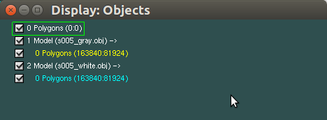
The 3D graphics objects, as displayed in the 3D window, are also presented in a hierarchical form in the object list window, as a tree structure with each element of the tree being the name of a 3D graphics object. There are 4 keys that can be used to navigate through the list, where the currently selected object is always displayed with a surrounding box:
Prev
Sets the current object to the previous item in the object list.
Next
Sets the current object to the next item in the object list.
6.2 File
The file menu groups a number of commands relating to loading and saving file data of various types.
File/Load Labels .mnc
Prompts for a filename and loads the file as the label volume for the current volume. The label volume need not have the same sampling or extent as the volume on top of which it is being loaded. This does not clear the current labels, unless the label file is exactly the same size and sampling as the underlying volume.
File/Save Labels .mnc
Prompts for a filename and saves the label volume of the current volume. The labels are cropped to the smallest size possible.
File/Load Labels .tag
Prompts for a filename and loads the tags file into the current label volume. Note that it does not clear the current label volume, so the resulting labels are the union of the current labels and the loaded tags. Also, it does not check that this is a valid label file, e.g., whether sizes match.
File/Save Labels .tag
Prompts for a filename and saves the current label volume as a tag file. For large regions this may create very large ASCII files, and it may be more efficient to save as .mnc.
File/Save Curr Lbl .tag
Prompts for a filename and saves voxels with the current label to a tag file.
File/Load UserDef ColCode
Prompts for a filename and loads the current user defined colour map as an ASCII file, with a default suffix of .ccd. It automatically switches the colour coding mode to user defined, in order to reflect the new map loaded from the file. Each line in file contains a position and a colour. The first position in the file must be 0, the last must be 1, and the intermediate ones must be monotonically increasing. The colours may be specified as 3 or 4 space separated values in the range 0 to 1, or as one of the predefined colour names. For instance, the gray colour scale is equivalent to a file with two lines, the first being 0 black, the second being 1 white.
File/Load Vertex Data
Loads a file of per-vertex data, such as cortical thickness measurements, and associates it with the currently selected object. The per-vertex data can be in most simple text formats, including “vertstats” format.
File/Save Mrkrs as .tag
Prompts for a filename and saves any markers at or under the current object to the file in tag file format.
File/Save Slice Image
If the mouse is pointing to one of the four slice viewports, prompts for a filename and saves the contents of the slice viewport to the file, in .rgb format. This will work for the intensity plot as well as the slice images.
File/Save File
Prompts for a filename and saves the current object, or all objects contained in the current object, if the current object is a model object. Files are typically saved in MNI .obj format, but single polygonal surfaces can also be saved in Stanford (.ply), X3D (.x3d), or Wavefront (.wf.obj) format. MNI Display will select the format based on the extension of the filename you supply.
This selection cannot be used to save a volume file.
File/Load File
Prompts for a filename and loads the file. If it is a volume file (ends in .mnc), then the slice window is opened, if not already opened.
File/Save Slice Window
Prompts for a filename and saves the contents of the slice window to the file, in .rgb format. Before doing this, make sure the window is up to date and not in the process of drawing.
File/Save 3D Window
Prompts for a filename and saves the image contents of the 3D window to the file, in .rgb format. Before doing this, make sure the window is up to date and not in the process of drawing.
File/Load Vertex Data
If the currently selected object is a polygon, this command will load per-vertex data to associate with this polygon. It will set the colours of the vertices appropriately, using the full range of the data and the spectral colour map. The file is assumed to be a text file (extension .txt, .tsv, or .csv), with exactly the same number of lines as there are vertices in the polygon.
File/Load Poly Visib.
Not for general use.
File/Save Poly Visib.
Not for general use.
File/Save Bintree
Not for general use.
File/Load Bintree
Not for general use.
File/Save Colour Map
Prompts for a filename and saves the label colour map of the current volume as an ASCII file, with a default suffix of .map. The label colour map is defined by Colour Coding/Set Paint Lbl Colour.
File/Load Colour Map
Prompts for a filename and loads the current label colour map as an ASCII file, with a default suffix of .map.
6.3 Intensity Plot
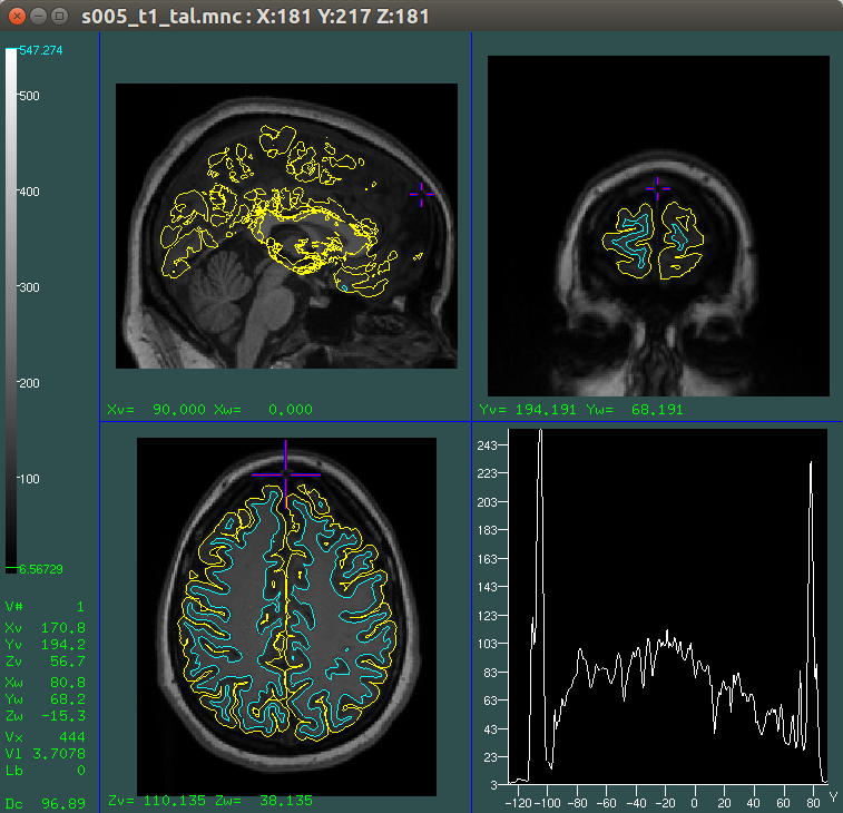
MNI Display can show a graph in the lower-right quadrant of the slice view window. This graph depicts the intensity values along a line through the current cursor position, parallel to one of the spatial axes. If a time axis is present, the intensity plot may also show the timecourse of the current cursor position or an ROI. The Intensity Plotmenu contains commands used to manipulate some of the options for displaying this data.
By default, the intensity plot is enabled and the horizontal axis is selected automatically using the following algorithm:
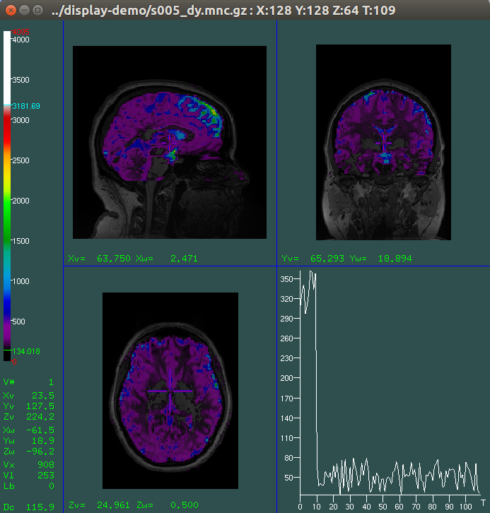
- If the current volume has a time dimension, the intensity of the current cursor location is plotted through time.
- If a measurement line has just been drawn, the intensity plot is taken along that line.
- If the mouse is over the sagittal view, the intensity plot is taken along the Y (posterior-anterior) axis.
- If the mouse is over the coronal view, the intensity plot is taken through the Z (inferior-superior) axis.
- If the mouse is over the transverse view, the intensity plot is taken through the X (left-right) axis.
In each case, a letter ’X’, ’Y’, ’Z’, or ’T’ will be displayed on the horizontal plot axis to indicate which of the axes is being used. If a measurement line is plotted, the horizontal axis simply shows the length in ’mm’ along the line.
As explained above, when a time-varying (e.g. fMRI, DWI, or PET) image is loaded, the intensity plot will automatically be computed using the time axis. Furthurmore, whenever the image is segmented, the labels will be used to define regions of interest whose mean intensity will be plotted over the timecourse of the ROI.
For example, if you load an fMRI image and wish to examine the timecourse of an specific region of interest, first paint the ROI using the segmenting features of MNI Display. Then, move the cursor inside the ROI. The intensity plot will change colour to reflect the colour of the ROI’s label. The intensity values will be computed as the unweighted mean of all voxels with the selected label, for each time point in the image.
When displaying a line along a spatial dimension, the background colour of the intensity plot will now reflect the labeling of voxels along the line. This is intended to help guide labeling by showing changes in intensity superimposed on the labels. The colours of the background will be immediately updated as changes are made to the labeling.
In any case, the intensity plot will be automatically disabled whenever the oblique image is enabled.
Intensity Plot/Enabled: On
Toggles the intensity plot on or off. If for some reason you do not wish to see intensity plots, they can be disabled with this menu option.
Intensity Plot/Scaled: On
If this option is on, the vertical axis of the intensity plot will be automatically scaled to the actual data range of the currently selected data. If this option is off, the vertical axis will be permanently set to the full range of the voxel intensities of this volume.
Intensity Plot/Axis: Auto
This option allows to you specify a preferred choice for the horizontal axis in the intensity plot. This command allows you to cycle through the choices Auto, X, Y, and Z. The time dimension, T, is also available for time-varying scans. The Auto mode uses the logic described above to set the horizontal axis based on the dimensions of the loaded volume and the position of the mouse cursor.
If one of the specific axes is selected, that axis will be used as the horizontal axis in the intensity plot irrespective of the current location of the mouse cursor. However, if a measurement line is drawn, the intensity along that line will still be displayed on the intensity plot axis.
6.4 Quit
The Quit menu’s main function is to allow users to explicitly confirm their intention to quit MNI Display. However, the menu includes a few miscellaneous commands.
Quit/Really Quit
Select this if you are sure you want to exit MNI Display. The program will close.
Quit/Don’t Quit
Select this if you do not want to quit MNI Display. You can also just press the space bar to return to the previous menu.
Quit/Show Memory
This command is intended for development and debugging purposes. It prints some possibly useful information about the memory usage of MNI Display.
Quit/Global Var
This command allows you to inspect or set the value of any of the many global variables (configuration options) that are supported in MNI Display. When you choose this command, it will prompt you to enter a string. The string can either be the name of a global variable, or a global variable name followed by an equals sign and a new value. In the former case, the command will print the current value of the global variable. In the latter case, the command will set the current value of the global variable.
For a list of many of the useful global variables in MNI Display, see Appendix B.
Quit/Save Layout
This command will save the current locations and sizes of all four windows (Menu, Slice View, Object List, and 3D View). The saved information will be used to restore the window layout the next time MNI Display is used. The information is saved in your home directory in a file named .mni-displayrc.
6.5 Slice View
The slice view menu is primarily concerned with manipulating the orientation and position of the three (or four) slice views. It also allows you to select which of the volumes is the currently active volume.
Moves the cursor to the next slice.
Moves the cursor to the previous slice.
Moves to the next time point in a dynamic scan.
Moves to the previous time point in a dynamic scan.
Slice View/Curr Volume
If more than one volume is loaded, then this button increases the current volume index. If the the last volume is currently selected, this will return to the index of the first volume. The current volume index is displayed in the lower left corner of the slice view, with the field title V#. For many operations, including intensity plots and colour-coding selection, the current volume is used as the target volume.
Slice View/Prev Volume
If more than one volume is loaded, then this button decreases the current volume index. If this command is chosen when the first volume is selected, the current volume index will be set to the last volume loaded.
Slice View/Reset Slice View
If the mouse is in the slice view window and is pointing to one of the 4 slices, then the view for that slice is reset and resized to fit the viewport.
Slice View/Toggle Slice Visibility
If the mouse is in the slice window and is pointing to one of the 4 slices, then the visibility of that slice for the current volume is toggled.
Slice View/Box Filter Volume
Prompts for 3 box filter widths and another specifier. If the specifier is the character “w”, then the filter widths are assumed to be in world coordinates, otherwise it is assumed to be voxel coordinates. The current volume is resampled using a box filter, creating new volume which is overlaid on the original volume.
Slice View/Resample Volume
Prompts for 3 size parameter and resamples the current volume to the given size, creating another volume. Creates a volume with a smaller number of voxels by box filtering. It is preferable to use Slice/Box Filter Volume, which maintains the number of voxels.
Slice View/Create 3D Slice
Creates and displays a flat, colourized rendering of the slice pointed to by the mouse in the 3D window.
Slice View/Create 3D Profile
Creates and displays a 3D object surface reflecting the relative intensities of the voxels in the current slice.
Slice View/Recompute Histogram
Creates a histogram of values in the current volume, which is displayed in the slice view window near the colour coding bar. If the mouse is pointing to a slice in the slice view window, then the histogram of only that slice of the current volume is displayed.
Slice View/Histogram of Label
Same as Slice View/Recompute Histogram, but only includes values which are in labeled (segmented) regions.
Slice View/Toggle Plane Visibility
This menu selection toggles the visibility of the cross section plane in the 3D View window.
Slice View/Set Current Arb. View
Each of the four slices can be oriented to an arbitrary angle. By pointing to one of the slices and selecting this menu option, the user can set the current arbitrary view, which is the one that the following slicing commands operate on.
Slice View/Toggle Slice Crs-Sect
Turns on or off the visibility of the cross-section plane in the three views which are not the current arbitrary view.
Slice View/Rotate Slice
After selecting this entry, the middle mouse button in the 3D window will control rotation of the arbitrarily oriented slice, updating the current view slice in the slice window.
Slice View/Pick Slice Angle
Instead of rotating the slice in the 3D window, the orientation of the current view slice can be chosen from within the slice window. After selecting this command, the left mouse button selects a position on one of the other slices. The line through the slice cursor and this position is used to define the slice plane of the current view slice.
Slice View/Toggle Slice Anchor
Turns on and off the anchoring of the current view slice to pass through the cross section of the current slice view. This is used to constrain a slice plane to pass through a given vector.
Slice View/Print Origin
Prints the cursor location in world space in the terminal window.
Slice View/Print Plane Normal
Prints the world space normal of the slice currently under the mouse.
Slice View/Type In Origin
Prompts the user to type in a world space x, y, and z, and moves the cursor to this point.
Slice View/Type In Plane Normal
If the mouse is pointing to one of the four slices, prompts the user to type in a world space x, y, and z, and orients the slice plane to this normal.
Slice View/Visible:
Makes only one volume visible, cycling through all loaded volumes as the button is pressed. Whichever volume is made visible is set to the current volume.
Slice View/Make All Visible
Make all of the volumes visible again.
Slice View/Vol Opacity:
Prompts the user for an opacity value and sets the opacity of the current volume.
6.6 Volume Config
This menu includes several miscellaneous commands, as well as two sets of options for controlling the filtering or smoothing of data in the Slice View window.
The global interpolation command, Volume Config/Interp:, changes the interpolation method used for all volume accesses. As such, it will change both the volume display and the specific values shown in the Slice View status. This interpolation smooths across all of the dimensions of the volume.
The per-view interpolation methods only affect individual views (the sagittal, coronal, or transverse planes). This interpolation occurs only between slices, perpendicular to the slice view plane. The filter width setting controls how many slices will be included in the filtered display.
Volume Config/Nearest Neighbour
Sets the filter type of the current volume slice under the mouse to nearest neighbour (this is the default).
Volume Config/Linear Int Filter
Sets the filter type of the current volume slice under the mouse to linear interpolation between the two nearest slices.
Volume Config/Box Filter
Sets the per-view filter type of the volume slice under the mouse to a box filter. If the mouse is not over a slice view, this command has no effect.
Volume Config/Triangle Filter
Sets the per-view filter type of the volume slice under the mouse to a triangle filter. If the mouse is not over a slice view, this command has no effect.
Volume Config/Gaussian Filter
Sets the per-view filter type of the volume slice under the mouse to a Gaussian filter. If the mouse is not over a slice view, this command has no effect.
Volume Config/Filter Width
Prompts the user for the full width half maximum for the per-view filter of the slice view under the mouse. Each view has its own filter width. This value applies only to box, triangle, or Gaussian filters. It does not apply to the nearest-neighbour or linear filters. If the mouse is not over a slice view, this command has no effect.
Volume Config/Interp:
Toggles the global interpolation method used for rendering slice images for the entire volume. The choices are nearest neighbour (the default), trilinear, and tricubic. This setting will affect the values shown in the Slice View status display, as they will also be interpolated.
Volume Config/Delete Volume
Brings up a submenu that allows the user to delete the current volume. This does not affect the file from which the volume was loaded, it merely removes the volume from memory.
Volume Config/Share Labels
Toggles whether or not segmenting labels are shared across volumes with identical sampling. If this option is Off, each loaded volume is associated with its own independent label volume. If this option is On, the default, a single label volume will be shared between all volumes with identical sampling grids. Sharing labels allows users can paint a single set of labels on several similar volumes, such as T1 and T2 volumes of the same patient.
Volume Config/Increm Update:
Toggles the incremental update mode of the slice window. When it is on, the slice window incrementally updates the slice window. This may still be useful when the slice window takes a long time to update, such as with cached volumes or in trilinear interpolation mode.
6.7 Volume Cropping
This menu allows the user to specify a subregion of a volume and to create new volumes that are cropped to this region.
Volume Cropping/Visibility:
Toggles the visibility of the volume crop box in the slice planes. Note that the position of the volume crop box is relative to the current volume, so changing the current volume will change the appearance of the crop box.
Volume Cropping/Reset Crop Position
Resets the volume crop box to the entire volume of the current volume.
Volume Cropping/Pick Crop Box
After pressing this selection, an edge, a corner, or the entire crop box in the slice window can be moved by pressing the left mouse button and dragging to the desired position.
Volume Cropping/Set Crop Source
Prompts the user to type in the name of the file which will be cropped according to the crop box.
Volume Cropping/Crop and Load
Crops the current crop filename with the current crop box volume limits, and loads the cropped file.
Volume Cropping/Crop to File
Prompts for a filename and creates the cropped volume as this file, without loading it.
6.8 Colour Coding
When you initially load a volume file, it will be displayed with the default HOT METAL (red-yellow) colour coding. Use this menu to switch to other colour coding scales, or to set colour values for labeled voxels.
Colour Coding/Spectral
Selects the spectral colour coding method for the current volume.
Colour Coding/Gray Scale
Selects the gray scale colour coding method for the current volume.
Colour Coding/Hot Metal
Selects the hot metal colour coding method for the current volume.
Colour Coding/Red
Selects the red colour coding method for the current volume.
Colour Coding/Green
Selects the green colour coding method for the current volume.
Colour Coding/Blue
Selects the blue colour coding method for the current volume.
Colour Coding/Arb Colour (Over)
Selects the colour coding method for the current volume, where the scale ranges from black through to the current over colour, which can be any valid colour.
Colour Coding/UserDef ColCode
Selects the colour coding method for the current volume, where the scale is defined by the user as any piecewise linear function. At present the only way to specify this function is through the File/Load UserDef ColCode function.
Colour Coding/Contour
Selects the rarely used contour colour coding method for the current volume.
Colour Coding/Range
Prompts the user to type in the lower and upper colour coding limits for the current volume. These may be the same, which results in a binary thresholded volume coloured by the under and over colour. The upper limit may be a smaller number then the lower limit, which results in an inverted colour map,
Colour Coding/Under Col
Prompts the user to type in the colour for values in the current volume below the low limit.
Colour Coding/Over Col
Prompts the user to type in the colour for values in the current volume above the high limit.
Colour Coding/Label Opacity
Prompts the user to type in the intensity of the coloured labels superimposed on the current volume slices. (0 <= value <= 1).
Colour Coding/Show Labels
Toggles between showing or hiding the label volume superimposed on the current volume.
Colour Coding/Set Paint Lbl Colour
Prompts for a label value and a colour, and sets the displayed colour of this label for the current volume.
Colour Coding/Num Labels
Prompts for the number of labels desired, and recreates the current label volume with this number. Depending on the number of labels, the volume may be a byte, short, or long valued volume. Note that this effectively clears the current label volume.
Colour Coding/Colour Code Objects
Changes the colours of the current object in the 3D window according to the current colour coding parameters of the loaded volumes. This copies both the colours of any visible volumes as well as their associated labels.
Colour Coding/Label Objects
Changes the colours of the current object in the 3D window according to the current colours of any visible labels, ignore the colours associated with the volumes.
6.9 Segmenting
This menu contains all the controls for modifying the current label volume, which is overlaid on the current volume. For each voxel in the current volume, there is an associated integer value, which is stored in the current label volume. Segmenting consists of painting regions of a label volume to change the values from the default of 0. When the right mouse button is pressed over a slice in the slice window, the current paint label value is painted into the label volume of the most recently loaded visible volume.
6.9.1 Erasing
The default value of all labels is zero, which is considered to be the “erased” value. The erased value can be changed through the menu commands If the control key or shift key is held down along with the right mouse button, erasing will be performed, by storing the value 0 (or the current erase value, if it has been set to something other than zero).
6.9.2 Secondary brush
MNI Display implements a secondary brush size which can be quickly selected as an alternative to the primary brush size. This allows rapid switching from fine-grained to coarse-grained painting. By default the secondary brush is a sphere 3 units in diameter. The Ctrl+B key combination is used to toggle between these brushes, and the menu commands to set the brush size will set the size of the current brush.
Segmenting/Clear All Labels
Sets all labels of the current volume to the erased state. Provides a cancel/confirm submenu, but cannot be undone.
Segmenting/Set Paint Label
Sets the current label used for painting. If the mouse is positioned over a voxel that has a non-zero label when this menu command is selected, then the current paint value is copied from that voxel. Otherwise, the user is prompted to type in an integer label, between 0 and one less than the total number of labels.
Segmenting/Set Erase Label
Sets the current label value used for erasing. If the mouse is positioned over a voxel that has a non-zero label when this menu item is selected, then the current erase value is copied from that voxel. Otherwise, the user is prompted to type in an integer label, between 0 and one less than the total number of labels.
Segmenting/XY Radius
Prompts for the in-slice brush radius (i.e. both the width and height) used in painting on the volume slices. Any voxel which intersects the brush is painted. A radius of zero therefore paints only voxel the mouse is in. This gives the finest control over painting.
Segmenting/Out-Plane Radius
Prompts for the brush depth, the radius in the direction perpendicular to the slice plane. This defaults to zero, for slice-by-slice painting. If this is non-zero, then a ellipsoidal brush is used, and updating the display is a little slower because all slice views are updated as painting is performed.
Segmenting/Undo
Reverses the last painting or erasing operation which, in many cases, may be used to reset the state of the labels to before the previous operation. Operations that affect many different slices, such as loading labels from a file, or a 3D operation such as 3D fill, cannot generally be undone.
Segmenting/Label Voxel
Sets the label of the voxel underneath the mouse to the current paint label. Can be undone.
Segmenting/Clear Voxel
Sets the label of the voxel underneath the mouse to the current erase label. Can be undone.
Segmenting/Label Slice
Sets the label of the entire slice pointed to by the mouse to the current paint label. Can be undone.
Segmenting/Clear Slice
Sets the label of the entire slice pointed to by the mouse to erase label. Can be undone.
Segmenting/Set Threshold
Prompts for a minimum and maximum volume value, and uses these limits for subsequent segmentation operations. When painting with the right mouse button, only voxels whose values are within this range are affected. Operations such as dilation, erosion, and 2D and 3D filling are also affected by the current threshold. By default, there is no segmenting threshold, which can be explicitly specified, if desired, by a maximum value which is less than the minimum value.
Segmenting/Label Fill
If the mouse is pointing to a voxel which is within the selected segmenting range and which has a label not equal to the current paint label, then all similarly labeled voxels on this slice connected to the starting voxel are assigned the current paint label, by a flood fill algorithm. Can be undone.
Segmenting/Label Fill No Thrs
Same as Segmenting/Label Fill, except ignoring the threshold. If the mouse is pointing to a voxel has a label not equal to the current paint label, then all similarly labeled voxels on this slice connected to the starting voxel are assigned the current paint label, by a flood fill algorithm.
Segmenting/Clear Fill
If the mouse is pointing to a voxel which is within the selected segmenting range and which has a nonzero label, then all similarly labeled voxels on this slice connected to the starting voxel are assigned the erase label value, by a flood fill algorithm.
Segmenting/Connectivity
Toggles between using 8 (or 26)-neighbour and 4 (or 6)-neighbour connectivity in 2D (3D) operations such as fill, dilate, and erode.
Segmenting/Erode 3D
Prompts the user for a label range which corresponds to outside the labels of interest, and erodes regions of the current paint label which are neighbouring the typed-in label range. Typically the user will type in “0 -1” to specify all labels which are not equal to the current paint label. Cannot be undone.
Segmenting/Dilate 3D
Prompts the user for a label range which corresponds to outside the labels of interest, and dilates regions of the current paint label which are neighbouring the typed-in label range. Typically the user will type in “0 -1” to specify all labels which are not equal to the current paint label. Cannot be undone.
Segmenting/Copy from Rt/Sup/Ant
If the mouse is pointing to a slice in the slice window, then the labels of the neighbouring slice are copied to this slice. For transverse slices, the neighbour is the slice just superior to this one. For coronal slices, the neighbour is the slice just anterior to this one. For sagittal slices, the neighbour is the slice just to the right of this one. Can be undone.
Segmenting/Copy from Lt/Inf/Pos
If the mouse is pointing to a slice in the slice window, then the labels of the neighbouring slice are copied to this slice. For transverse slices, the neighbour is the slice just inferior to this one. For coronal slices, the neighbour is the slice just posterior to this one. For sagittal slices, the neighbour is the slice just to the left of this one. Can be undone.
Segmenting/Fill 3D
If the mouse is pointing to a voxel which has a label which is not equal to the current paint label and is within the threshold, then all similarly labeled voxels in the entire volume which are connected to this one are assigned the current paint label. This may take a few seconds to a minute. Cannot be undone.
Segmenting/Calculate Volume
Calculates the total volume of all voxels which have the current paint label. This may take few seconds to complete.
Segmenting/Change Labels
Replaces a label, or a range of labels, with a new label value. Prompts for a source label or label range, a destination label value, and as a volume value minimum and maximum value. All voxels which have the source label value and are within the specified value range are changed to have the destination label. If the maximum value specified is less than or equal to the minimum value, then this range is ignored, and the operation simply changes all occurrences of the source label to the destination label.
Segmenting/Fast Update
Toggles between updating only the slice on which the mouse is painting or all slices, in order to provide a speed tradeoff. By default, fast update is on, which results in fast painting.
Segmenting/Cursor Follows
Toggles the mode where the slice cursor follows the mouse during painting. This results in slower update speeds, but all slice views show updated labels as painting progresses, which may be helpful for detail work.
Segmenting/Cursor Vis
Toggles the visibility of the crosshairs cursor in the slice view window.
Segmenting/Freestyle
Toggles freestyle painting, where the brush follows every movement of the mouse, and straight-line painting, in which straight line segments are drawn between successive right mouse clicks.
Segmenting/Enable Undo
Toggles the state of the undo feature. Allows the undo logic to be enabled or disabled.